Grease Trap Drawings Design
Grease Trap Drawings Design - Web grease retention capacity = (flow rate x hours of operation) / (1000 x grease removal efficiency)2. 35 gpm grease trap cad drawings zip file. • the grease trap size shall be based on a minimum hydraulic detention time of 36 hours; 25 gpm grease trap cad drawings zip file. Web 3.02 grease traps shall be installed at a minimum distance of 10 ft. 20 gpm cad drawings zip file. Where a capacity of more than 4.7 m3 is required, two or more grease traps may be placed in a series. 1003.3.3 grease trap and grease interceptor not required. Water temperatures must be less than 120 degrees prior to entering grease trap. Choose the appropriate grease trap type based on the flow rate and available space. 25 gpm grease trap low profile cad drawings file. Its design should also allow for the easy removal of the cover for maintenance works. 15 gpm cad drawings zip file. The size of the grease trap depends on the anticipated flow rate, water temperature, and grease concentration. 25 gpm grease trap cad drawings zip file. If commercial dishwashers are discharged through a grease interceptor, care must be taken in system design. 25 gpm grease trap low profile cad drawings file. 35 gpm grease trap cad drawings zip file. By downloading and using any arcat cad drawing content you agree to the following license agreement. And • minimum tank size of 1,000 gallons. 25 gpm grease trap cad drawings zip file. Web displaying grease trap design drawing.pdf. 15 gpm cad drawings zip file. If commercial dishwashers are discharged through a grease interceptor, care must be taken in system design. Web cad drawings & submittal sheets for grease traps; 25 gpm grease trap low profile cad drawings file. 20 gpm cad drawings zip file. 1003.3.3 grease trap and grease interceptor not required. 635 pounds (288 kg) 75 gpm (4.73 l/s) view/download pdf: 15 gpm cad drawings zip file. Our injection molding expertise and. 35 gpm grease trap cad drawings zip file. Web grease retention capacity = (flow rate x hours of operation) / (1000 x grease removal efficiency)2. 20 gpm cad drawings zip file. 50 gpm grease trap cad drawings zip file. Web cad drawings for grease traps: Based on the principles of hydromechanical design, our grease interceptors use engineered thermoplastics. 25 gpm grease trap cad drawings zip file. 25 gpm grease trap cad drawings zip file. 25 gpm grease trap low profile cad drawings file. Our injection molding expertise and. 1003.3.3 grease trap and grease interceptor not required. • the outlet shall be protected with a baffle that extends downward and terminates 6 inches from the inside bottom of the grease trap. Web cad drawings for grease traps: By downloading and using any arcat cad drawing content you agree to the following license agreement. 25 gpm grease trap cad drawings zip file. 7 gpm cad drawings zip file. Web in this comprehensive guide, we delve into the world of grease trap design drawings, providing you with the knowledge and insights to create a system that meets your specific needs. 15 gpm cad drawings zip file. 1003.3.3 grease trap and grease interceptor not required. Web free grease traps architectural cad drawings and blocks for download in dwg or pdf formats for use with autocad and other 2d and 3d design software. The size of the grease trap depends on the anticipated flow rate, water temperature, and grease concentration. 635 pounds (288 kg) 75 gpm (4.73 l/s) view/download pdf: 50 gpm grease trap cad drawings. • the outlet shall be protected with a baffle that extends downward and terminates 6 inches from the inside bottom of the grease trap. Determine the size of the trap using the grease retention capacity calculated in step 1. Web model grease capacity rating certified flow rate specification sheets cad drawings; If commercial dishwashers are discharged through a grease interceptor,. Web 3.02 grease traps shall be installed at a minimum distance of 10 ft. Its design should also allow for the easy removal of the cover for maintenance works. 15 gpm cad drawings zip file. Web cad drawings for grease traps: 20 gpm cad drawings zip file. Our injection molding expertise and. 20 gpm cad drawings zip file. 50 gpm grease trap cad drawings zip file. Water temperatures must be less than 120 degrees prior to entering grease trap. From understanding the significance of grease traps to the intricate details of their design, we leave no stone unturned. In general, grease traps range from a minimum capacity of 2.8 m3 to a maximum capacity of 4.7 m3. 15 gpm cad drawings zip file. 25 gpm grease trap low profile cad drawings file. From sinks and dishwashers to allow for adequate cooling of the wastewater. If commercial dishwashers are discharged through a grease interceptor, care must be taken in system design. Web grease retention capacity = (flow rate x hours of operation) / (1000 x grease removal efficiency)2. Our injection molding expertise and. Based on the principles of hydromechanical design, our grease interceptors use engineered thermoplastics. Where a capacity of more than 4.7 m3 is required, two or more grease traps may be placed in a series. 25 gpm grease trap cad drawings zip file. Web cad drawings & submittal sheets for grease traps; Web in this comprehensive guide, we delve into the world of grease trap design drawings, providing you with the knowledge and insights to create a system that meets your specific needs. Grease traps play a vital role in preventing oily and greasy substances from entering the sewer system, which can cause blockages and foul odors. Select grease trap type and size. 1003.3.3 grease trap and grease interceptor not required. • the grease trap size shall be based on a minimum hydraulic detention time of 36 hours;
Commercial Grease Trap Installation Diagram
Detail Grease Trap Design Drawings
grease trap piping diagram RehanMykenzie

Grease Trap Free CAD Block And AutoCAD Drawing

Kitchen Grease Trap Design Drawings Design Talk

Grease Trap Design Drawings Design Talk
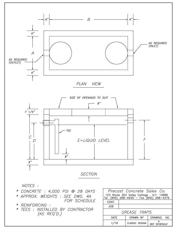
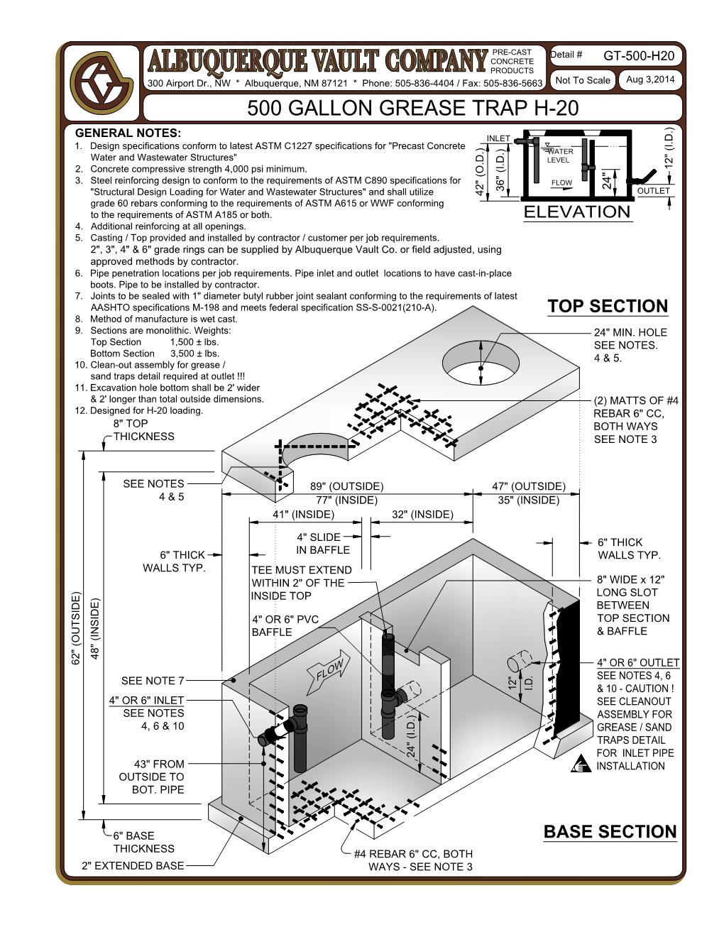
Grease Traps Precast Concrete Sales Company

grease trap autocad drawing vanlifetshirt

Solid Works Commercial Kitchen Grease Trap Design YouTube
Grease trap design in AutoCAD 2D drawing, CAD file, dwg file Cadbull
20 Gpm Cad Drawings Zip File.
And • Minimum Tank Size Of 1,000 Gallons.
Pot Sink Grease Trap Sizing Chart.
Web Autocad Dwg Format Drawing Of A Grease Trap Chamber Detail, Plan, Front, And Side Elevation 2D Views For Free Download, Dwg Block For Sanitary Installation Details.
Related Post: